


In a worldview that values environmental protection and sustainability, companies involved in oil and natural gas extraction need to make their production processes cleaner, more efficient, and more economical. Artificial lifting is one of the wise choices to achieve this. By providing real-time pressure data, wellhead pressure transmitters enable operators to make informed decisions during the entire lifting cycle, from initial well assessment and setup to the actual lifting process and subsequent maintenance procedures. Additionally, wellhead pressure monitoring ensures regulatory compliance and optimizes production. MICROSENSOR supplies both smart transmitters with local display for critical wellhead control points, and cost-effective analog-output sensors for distributed pressure monitoring. This hybrid configuration helps our customers balance performance, visibility, and budget.

What is Artificial Lift (Especially for plunger lift, gas lift)?
Artificial lift in the oil and gas industry refers to techniques used to increase the flow of fluids from a well when the natural reservoir pressure is insufficient to lift the fluids to the wellhead. It essentially boosts well productivity by artificial means. Compared to electric submersible pumps (ESPs), plunger lift or gas lift is a more economical option for various well conditions and production scenarios, particularly for wells with a high gas-to-liquid ratio (GLR).
Plunger lift aims to remove liquids (water, oil, or other contaminants) that accumulate in the wellbore, preventing them from hindering production. A plunger (a free-acting piston) is installed in the well's tubing string. When liquids accumulate in the well, the plunger is raised to the surface by the well's gas pressure. This process creates a mechanical seal that traps the gas and builds pressure, allowing the plunger to lift the liquids to the surface. Once the liquids are removed, the plunger returns to its starting position, and the process repeats.
Gas lift injects high-pressure gas (typically nitrogen or natural gas) into the well to reduce the fluid density, making it easier for the fluids to flow to the surface. Combining the gas lift and plunger lift technology can maximize production at different production stages of the well under a consistent flowing tubing pressure.
No matter which of the artificial lifting methods we're mentioning, one key physical quantity stands out: PRESSURE. Pressure measurement for plunger lift or gas lift plays a crucial role at every stage of the system, even in crucial elements of oil and gas extraction operations, such as tubing, casing, wellhead, or flow line.
How to Measure Pressure in Plunger Lift?
In plunger lift systems, several key pressures need to be measured and monitored for optimal performance and troubleshooting: casing pressure and tubing pressure.

Casing Pressure
This pressure builds up in the annulus (the space between the well casing and tubing) during the shut-in phase of the plunger lift cycle. The gas pressure from the reservoir helps to lift the accumulated liquid and plunger to the surface when the surface valve opens. Casing pressure helps determine if the well is being properly loaded with liquid.
Tubing Pressure
Tubing pressure is the pressure inside the production tubing itself. This pressure changes as the plunger moves down the tubing and as the well produces. When the surface valve opens, the tubing pressure quickly drops to line pressure, allowing pressurized gas from the annulus to enter the tubing below the plunger. This gas then pushes the plunger and the fluid column above it to the surface.
What Pressure Should Be Measured in Gas Lift?
Both the plunger lift and the gas lift utilize well casing and production tubing as part of their base operation structure. The difference is that gas is injected into the well's annulus in a gas lift system. The following breakdown of the pressure measurements in the gas lift system, monitoring performance, and optimizing production rates:

Injection Gas Pressure
Surface injection pressure is when gas is injected into the well's annulus (the space between the casing and tubing), typically measured at the surface. The injection pressure needs to be sufficient to overcome the hydrostatic pressure of the fluid in the tubing and initiate flow.
Downhole Casing Pressure
The pressure of the injection gas at the depth of the gas lift valve (GLV). It can be used in conjunction with the surface injection gas pressure to determine the differential pressure, which is critical for valve operation. The pressure is required to open the gas lift valves and allow injection gas to enter the production tubing. It is essential for designing and optimizing the gas lift system.
Production Tubing Pressure
This is the pressure of the fluid (oil, gas, and water) flowing up the tubing. It's an important indicator of the well's production performance.
Pressure Transmitters for Plunger Lift & Gas Lift
Challenge
Pressure transmitters are typically installed at the wellhead or production tubing — often on the tubing head or "Christmas tree" — to measure tubing or casing pressure at the wellhead of the oil &gas well. Challenges in pressure measurement for artificial lift systems primarily stem from the unique operating conditions and the dynamic nature of the process.
Harsh Operating Environment: Wellhead environments can be harsh, with fluctuating temperatures, corrosive fluids. There is a risk of explosion in gas lift, particularly. The wellhead pressure transmitters must be explosion-proof with properly temperature-compensated to withstand these conditions.
Pressure Variations: The necessitates of oil well pressure instruments with a wide range to accurately capture both the high-pressure spikes and the lower pressures during normal flow.
Real-time Data Feedback: Accurate tubing & casing pressure measurement is only the first step. The acquired data must be real-time processed and analyzed to gain meaningful insights into well performance and optimize operations.
Recommended Products
When MICROSENSOR automated, and smart pressure transmitters are combined with economical artificial lift, real-time pressure data helps optimize the lift cycle, monitor well conditions, and ensure safe and efficient operation. We supply both smart pressure transmitters with local display for critical wellhead control points, and cost-effective analog-output sensors for distributed pressure monitoring. This hybrid configuration helps our customers balance performance, visibility, and budget.
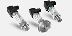
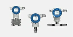
MPM483DM Explosion-Proof Pressure Transmitters for Wellhead
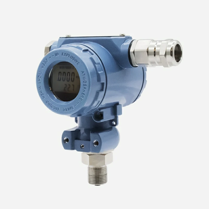 | · Measure range:-1bar…0bar ~ 100mbar…1000bar · High accuracy with MODBUS RS485 output · LCD display, corrosion-resistant housing · Optimized for distributed wellhead automation · Seamless integration with PLCs, RTUs, and SCADA systems · Intrinsically safe and explosion-proof certification |
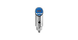
MPM489 Transmitter for Oil and Gas Extraction
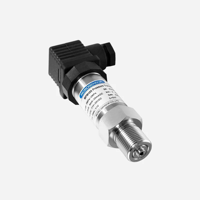 | · Ideal for a standardized wellhead control panel(WHCP) · Small size, easy installation, and cost-effective · Integrated with RTU/PCL for real-time monitoring and control · CSA, ATEX, and IECEX certified for hazardous area use |
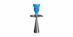
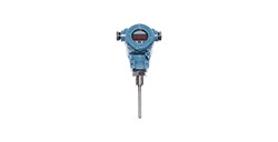
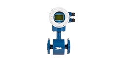
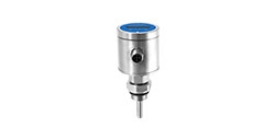
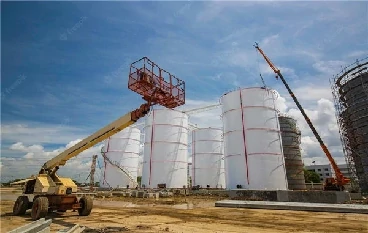
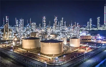
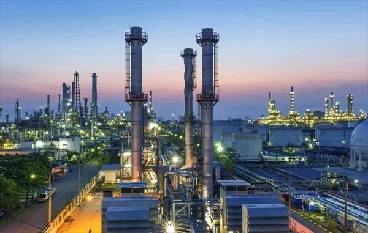
As an experienced pressure transmitter manufacturer, MICROSENSOR is dedicated to providing pressure transmitters in the oil & gas industry to help optimize production results on plunger lift or gas lift solutions and installations. In addition to wellhead pressure monitoring and control, our pressure, level, flow, and temperature measurement solutions support you in other oil and gas applications, such as pipeline monitoring, storage tank monitoring, etc. Contact us and let's begin optimizing your oil & gas production!


 Copyright © 2026 MICRO SENSOR CO., LTD
