


The printing and dyeing industry is with high energy consumption, high water consumption, and high pollution. In recent years, energy conservation and emission reduction have become a trend in China's industrial development. Some of the more polluting enterprises are facing strict national policy restrictions, which has accelerated the development of the printing and dyeing wastewater treatment industry.

Background
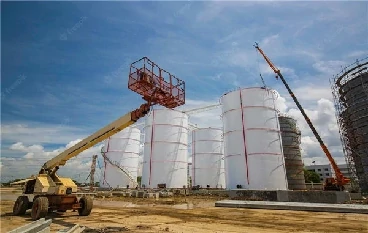
The mentioned printing and dyeing factory is a large-scale private joint-stock enterprise with a production history of more than 70 years. The factory covers an area of 160,000㎡. It has a provincial-level technical center and a textile import and export inspection platform. The inspection facilities are complete, and it meets the testing standards of AATCC and the European Union. It is a provincial clean production test enterprise owning power plant, water supply plant, and sewage treatment plant.
Our MFE600 separated electromagnetic flow meter and outer surface mount ultrasonic flow meters are used in many sites of the process chain in the printing and dyeing workshop:
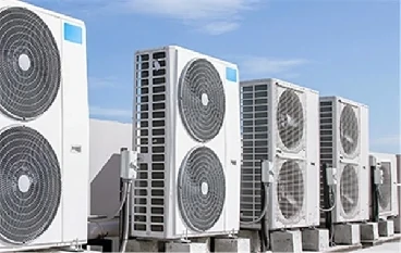
1. The measurement of intake water of the dyeing machine in the water inlet section;
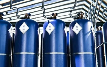
2. The transportation and measurement of dyes in the automatic weighing system;
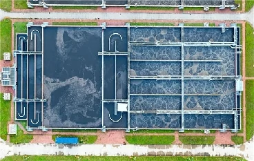
3. The measurement of discharge of printing and dyeing wastewater
Problems

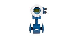
MFE600 separated electromagnetic flowmeter?

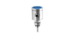
TUF2000 Ultrasonic Flowmeter
Onsite failures of flow meter usage:
1. The instantaneous flow rate of multiple electromagnetic flow meters is negative, or there is flow but the instantaneous flow rate is zero. The electromagnetic flowmeter has no display when the power’s on.
2. The surface-mounted ultrasonic flow meter has no reading.
Solutions
After receiving the customer's feedback, our technical team immediately went to the customer site to solve the application problem. After troubleshooting the site environment and usage, we find the cause of the equipment failure:
(1) Root Cause: Two IP65 protected integrated electromagnetic flowmeters have no display. Because the position of the electromagnetic flowmeter is installed too close to the printing and dyeing equipment which will discharge a large amount of steam. The site environment is humid, the front and rear end covers of the electromagnetic flowmeter are not waterproof and without sealing treatment. The circuit is damped or soaked by water which results in a burn-out circuit.
Correction: Replace and seal the circuit board of the flow meter and the electromagnetic flowmeter runs normally.
(2) Root Cause: Multiple electromagnetic flowmeters has a negative flow rate. It is caused by incorrect installation location of the flow meter which does not meet the requirements of the straight pipe section of 5D in front of the flow meter and 3D behind it, thus the pipeline is not full and the flow field of the medium is unstable and bubbles are generated.
Correction: Change the installation position and problems are solved.
(3) Root Cause: The?ultrasonic flow meter has no flow display. It is caused by setting the parameters of the ultrasonic flow meter unreasonably. The ultrasonic external probe position is properly installed while other necessary setting parameters are not set according to actual requirements on site such as pipe diameter circumference, pipe wall thickness, pipe material.
Correction: After setting the parameters reasonably, the ultrasonic flow meter runs normally.
Onsite installation Tips
The proper part number selection of electromagnetic flowmeters is critical to the suitability of field applications. The customer’s working conditions shall be known very clearly before a suitable part number is chosen. For applications with many installation positions in large quantities, we recommend that technical engineers conduct on-site field conditions first, and they help customers to select correct products.
The onsite installation position of the electromagnetic flowmeter directly affects the accuracy of the flow measurement. The installation process must follow the requirements of the straight pipe section of 5D in front of the flow meter and 3D behind.
Ultrasonic flow meters are different from electromagnetic flowmeters. In order to get an accurate measurement, the relevant parameters shall be set correctly and accurately.
After field troubleshooting, the flow meters applied in the printing and dyeing factory are all working normally and in good working condition.
For any needs, feel free to contact us via email or leave messages.
Previous Posts: Electromagnetic Flow Meter Applied in Plate Heat Exchange Station
Next Chapter: Flow Measurement for Chemical Raw Materials Ratio
 Copyright © 2026 MICRO SENSOR CO., LTD
