
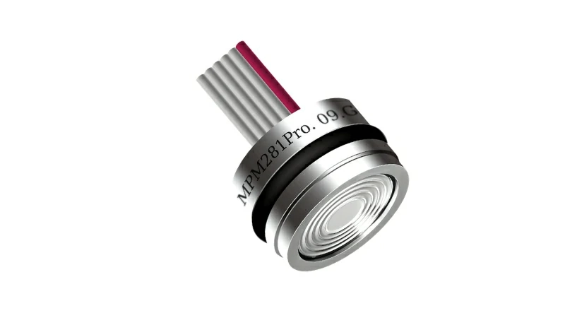
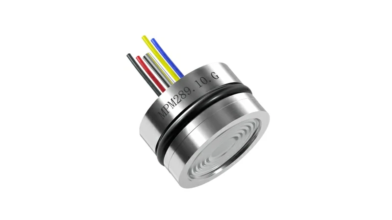
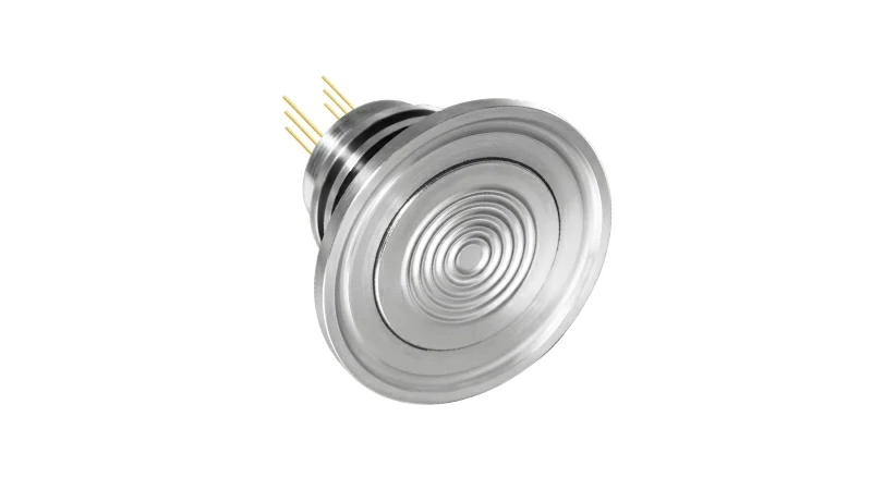
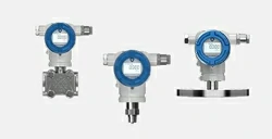
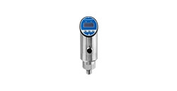









Piezoresistive silicon pressure sensors offer exceptional sensitivity, high linearity, and outstanding fast-response capabilities for industrial pressure measurement and control. These performance advantages stem directly from the physical properties of silicon, so too does their primary vulnerability: an extreme inherent sensitivity to temperature fluctuations. Even subtle thermal shifts can cause significant zero and span drifts, rendering sensor output unreliable in varying operating environments. Consequently, temperature compensation is not merely an optional performance upgrade—it is a critical design specification and essential quality benchmark.
The Physics Behind the Drift
A piezoresistive pressure element functions via four piezoresistors diffused into a silicon diaphragm, configured as a Wheatstone bridge. When pressure deforms the diaphragm, the resistance changes, creating a proportional voltage output. However, silicon's semiconductor properties dictate that its electrical resistance—and its piezoresistive coefficient—depend strongly on temperature. It manifests primarily in two distinct forms of measurement error when temperature fluctuates:
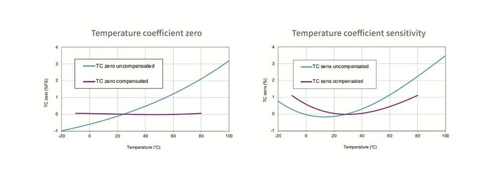
Zero Drift
Even without applied pressure, the change in sensor output voltage across varying temperatures. It stems from slight mechanical stress imbalances in the sensor packaging, thermal expansion mismatches in silicon-glass bonding, and minor resistor asymmetries in the Wheatstone bridge. As temperature changes, the zero-point voltage drifts, causing offset errors.
Sensitivity Drift (Span Drift)
Because the piezoresistive coefficient of doped silicon decreases as temperature rises, an uncompensated Wheatstone bridge exhibits a natural drop in sensitivity. The measured pressure readings will appear lower at high temperatures and higher at low temperatures.
The Hidden Risks of Uncompensated Thermal Drift
Operating an uncompensated silicon pressure sensor in varying thermal environments directly compromises measurement integrity. Left unaddressed, thermal drift creates cascading operational risks:
Costly Nuisance Shutdowns: Inaccurate feedback loops trigger false PLC/DCS alarms, leading to unnecessary valve shutoffs, process interruptions, and expensive operational downtime.
Equipment Damage & Safety Hazards: Undetected pressure surges caused by under-reported readings can exceed safe system limits, risking line bursts, fluid leaks, or structural failures in critical applications.
Increased Warranty & Field Service Costs: System integrators face high troubleshooting costs and premature replacements due to unexplained measurement inconsistencies across seasonal or daily thermal cycles.
Bridging the Gap: Where Temperature Compensation Comes into Play
Thermal drift generates non-negligible measurement errors that can be easily misread as real pressure fluctuations. This is precisely where temperature compensation comes into play. It ensures that the output signal reflects actual pressure changes across varying operating environments rather than thermal fluctuations.
Temperature compensation works by actively tracking real-time thermal changes and introducing counter-balancing corrections to neutralize drift before it reaches your control loop. At its core, this process transforms a temperature-sensitive silicon element into a stable, high-precision one, bridging the gap between inherent physical limitations and the demands of industrial measurement.
Common Methods of Temperature Compensation
In industrial pressure sensor manufacturing, temperature compensation is realized through two core technical approaches:
Method A: Analog Hardware Compensation (Resistor Trimming)
Hardware compensation was achieved by adding external passive resistors (such as laser-trimmed resistors) in series or parallel with the bridge circuit.
How it works: Constant current excitation is fed through a series resistor to boost bridge voltage as temperature rises, counteracting sensitivity drop.
Limitations: Analog trimming can only correct first-order linear temperature errors. Silicon’s thermal behavior is inherently non-linear; thus, residual second-order thermal errors remain, restricting overall accuracy across wide operating temperatures.
Method B: Digital Mathematical Model Compensation (Digital Signal Conditioning Technology)
Utilizes digital mathematical modeling to compensate for both linear and non-linear thermal drift across broad temperature spans, a digital signal conditioning technique driven by multi-point polynomial mathematical algorithms.
How it works: Rather than relying on analog components (like laser-trimmed resistors) that can only correct linear first-order errors, digital mathematical modeling uses microprocessors, Digital Signal Processors (DSP), or Application-Specific Integrated Circuits (ASIC) to calculate real-time mathematical corrections, enabling sensors to achieve ultra-low Total Error Band (TEB) specs.
Manufacturing Edge from MICROSENSOR
With over 50 years of mature manufacturing expertise in piezoresistive sensing elements, we combine time-tested automated laser trimming with ASIC digital signal conditioning, offering tailored, high-precision signal output for diverse application scenarios. Every sensor undergoes strict thermal burn-in aging and multi-point automated temperature calibration, guaranteeing long-term baseline stability and near-zero thermal drift in harsh field environments.
Whether you need high-stability piezoresistive OEM pressure sensing elements for custom integration or fully compensated, ruggedized pressure transmitters, our engineering team is ready to assist. Contact our application engineers today to request technical datasheets.
 Copyright © 2026 MICRO SENSOR CO., LTD


