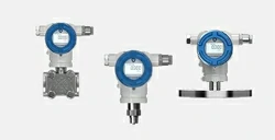


Low Range Pressure Transmitter
5mBar~0.2Bar
4~20mA DC
Accuracy: ±0.5%FS
New Product Change Notice (PCN) effective Jan 1, 2025. MICROSENSOR appreciate your understanding.

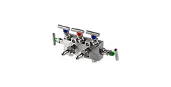
MV7000
The actuation of opening, closing, balancing, and venting operations of differential pressure transmitters and pressure transmitters
Leave a MessageMV7000
Used For
The actuation of opening, closing, balancing, and venting operations of differential pressure transmitters and pressure transmitters
Leave a MessageIntroduction
Valve manifolds are devices utilized for the actuation of opening, closing, balancing, and venting operations of differential pressure transmitters and pressure transmitters, controlling specifications such as fluid pressure, flow, and temperature. MV7000 series valve manifolds consists of shut-off valve, two-valve manifold (column), two-valve manifold, three-valve manifold, and five-valve manifold configurations.
Functions
• Shut-off valve (Code: N)
The function of the shut-off valve is to open or shut off the pipeline flow. During installation, it is crucial to ensure that the flow direction of the applicable medium aligns with the arrow direction marked on the valve body.
• Column two-valve manifold (Code: M)
The column two-valve manifold consists of a shut-off valve (for opening, closing or purging) and a vent valve (typically for debris, water, or air). It is crucial to ensure that the flow direction of the applicable medium aligns with the arrow direction marked on the valve body. The shut-off valve and the vent valve are are distributed at 180°.
• Two-valve manifold (Code: 2)
The column two-valve manifold consists of a shut-off valve (for opening, closing or purging) and a vent valve (typically for debris, water, or air). It is crucial to ensure that the flow direction of the applicable medium aligns with the arrow direction marked on the valve body. The shut-off valve and the vent valve are are distributed at 90°.
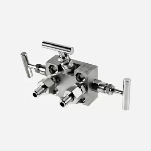
• Three-valve manifold (Code: 3)
The three-valve manifold consists of a valve body, two shut-off valves, and a balance valve. Based on the function of each valve in the system, it can be categorized as follows: the positive (upstream) globe valve, the negative (downstream) shut-off valve, and the balance valve located in between. The three-valve manifold is used in conjunction with a differential pressure transmitter to establish or isolate communication between the positive and negative pressure measuring chambers and the impulse point, or to isolate or establish communication between the positive and negative pressure measuring chambers.
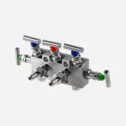
• Five-valve manifold (Code: 5)
The five-valve manifold is essentially a three-valve manifold with the addition of vent valves on both the high and low-pressure sides.
Image:
Introduction
Valve manifolds are devices utilized for the actuation of opening, closing, balancing, and venting operations of differential pressure transmitters and pressure transmitters, controlling specifications such as fluid pressure, flow, and temperature. MV7000 series valve manifolds consists of shut-off valve, two-valve manifold (column), two-valve manifold, three-valve manifold, and five-valve manifold configurations.
Functions
• Shut-off valve (Code: N)
The function of the shut-off valve is to open or shut off the pipeline flow. During installation, it is crucial to ensure that the flow direction of the applicable medium aligns with the arrow direction marked on the valve body.
• Column two-valve manifold (Code: M)
The column two-valve manifold consists of a shut-off valve (for opening, closing or purging) and a vent valve (typically for debris, water, or air). It is crucial to ensure that the flow direction of the applicable medium aligns with the arrow direction marked on the valve body. The shut-off valve and the vent valve are are distributed at 180°.
• Two-valve manifold (Code: 2)
The column two-valve manifold consists of a shut-off valve (for opening, closing or purging) and a vent valve (typically for debris, water, or air). It is crucial to ensure that the flow direction of the applicable medium aligns with the arrow direction marked on the valve body. The shut-off valve and the vent valve are are distributed at 90°.
• Three-valve manifold (Code: 3)
The three-valve manifold consists of a valve body, two shut-off valves, and a balance valve. Based on the function of each valve in the system, it can be categorized as follows: the positive (upstream) globe valve, the negative (downstream) shut-off valve, and the balance valve located in between. The three-valve manifold is used in conjunction with a differential pressure transmitter to establish or isolate communication between the positive and negative pressure measuring chambers and the impulse point, or to isolate or establish communication between the positive and negative pressure measuring chambers.
• Five-valve manifold (Code: 5)
The five-valve manifold is essentially a three-valve manifold with the addition of vent valves on both the high and low-pressure sides.


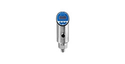
MDM7000-GP-T Accuracy:±0.1%、±0.2%URL
MDM7000-AP-T Accuracy:±0.1%、±0.2%URL
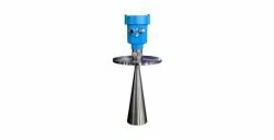
MDM7000-GP-T Range:0.4bar~100bar
MDM7000-AP-T Range:0.4bar~10bar
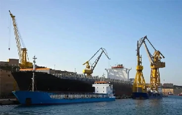
DNV, ABS, KR, NK, and RS approved for installation on vessels

Overpressure: 1.5 FS
Accuracy: ≤±0.25%FS; ≤±0.5%FS
Operation Temp.(controller): -25℃ ~65℃


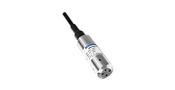
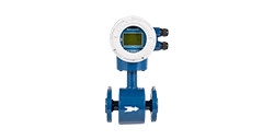
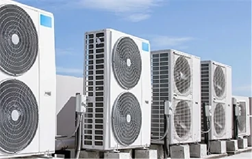
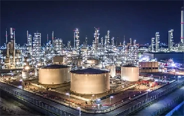
Pressure transmitters, temperature tranmitters and electromagnetic flowmeters are installed in the marine water circulation cooling system to ensure the heat exchange efficiency of the central cooler. By optimizing seawater flow control, energy saving effects are maximized and stable operation of the cooling system is ensured.
more info...
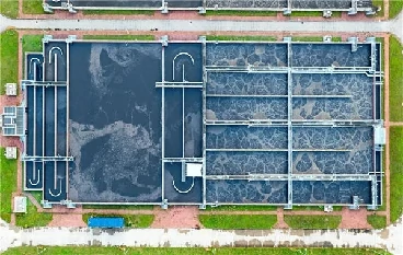
Pipelines are the most common water transportation and irrigation facilities. During transportation, pipelines effectively reduce evaporation and leakage of water resources. Magnetic flowmeters measure accurately discharge flow. It is a crucial action of rational water resource allocation and reasonable water fee collection.
more info...
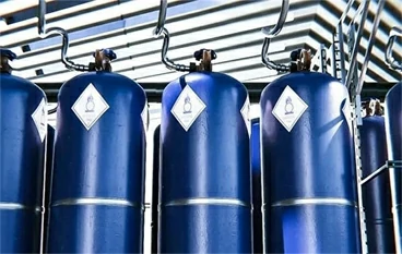
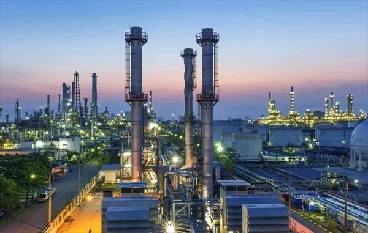
Dryers are often used to dry medicines or extract active ingredients from traditional Chinese medicines, which are easily decomposed in high temperature environments. Temperature measurement is required in the heating area, cooling area and material outlet of the dryer, and pressure transmitters are used to measure the pressure of air or gas to help adjust the air flow speed and fan operation status, or measure the pressure of steam, hot water, and hot oil pipelines.
more info...
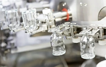
Before beer bottles, medicine bottles, and condiment bottles are filled with liquid, they need to be cleaned first. The cleaning process is as follows: First, the bottles are filled with lye in the alkali tank to remove most of the stains; then, the bottles are back washed with high pressure using water of different temperatures to wash away the remaining impurities and lye. To ensure the stable operation of the bottle washing machine, the level of the alkali tank needs to be measured by hydrostatic pressure. In addition, the pressure of the alkali tank water inlet pipe and the nozzle pipe also needs to be measured.
more info... Copyright © 2026 MICRO SENSOR CO., LTD


